
This chapter describes how to set software-configurable information for the Fiber Distributed Data Interface (FDDI) in the router.
This chapter contains the following sections:
Fiber Distributed Data Interface (FDDI) is described by the ANSI X3T9.5 and ISO 9314 committees as a dual counter-rotating ring that operates at a defined speed of 100 Mbps.
In many ways, FDDI is similar to the IEEE 802.5 token-ring, although there are differences, some of which are described in "Differences Between FDDI and Token-Ring".
FDDI is defined as a token-passing protocol. Each station has the chance to transmit data when a token passes. A station can decide how many frames it will transmit using an algorithm that permits "bandwidth" allocating.
FDDI also allows a station to transmit many frames without releasing the token in a way that is similar to the IEEE 802.5 token-ring standard.
An FDDI ring network consists of a set of stations/devices connected as a serial string of stations/devices and transmission media to form a physically closed loop. Information is transmitted sequentially as a stream of suitably encoded signals from one active station/device to the next active one.
Each station/device generally regenerates and repeats each token and can serve as the means of attaching one or more stations/devices to the network.
FDDI defines two rings:
Each ring path consists of two fibers, each fiber transmitting one signal; one is pushed and one is pulled in a device. Each fiber is equivalent to a pair of copper conductors. The physical approach in terms of fiber optics is similar to physical fiber optic token-ring paths.
FDDI permits many attachment units:
These units can be attached to FDDI networks in various ways, similar to those for token-ring networks.
The main differences between FDDI and token-ring techniques are:
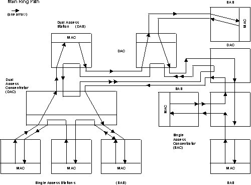
FDDI defines two device classes, A and B, to differentiate between devices that attach to one ring or both rings, as described in the next section.
FDDI defines two device classes:
It can be a station, called a Class A station or Dual Access Station (DAS), or it can be a Concentrator, called a Dual Access Concentrator (DAC)
It can be a station, called a Class B station or Single Access Station (SAS), or it can be a Concentrator, called a Single Access Concentrator (SAC)
Figure 14. FDDI Network Diagram. This diagram shows Single Access Stations (SAS), Dual Access Stations (DAS), Single Access Concentrators (SAC), and Dual Access Concentrators (DAC) in one Main Ring Path of an FDDI network.
